S/3 Model 15 Project Denmark 2014
In 2011 I made a start with the restauration project of a S/3 model 15D at the Dansk Datahistorisk Forening.
This is the blog of my second visit. Click here for the blog of my first visit.
IBM 3277-1 terminal
Since my first visit the IBM 3277-1 operator console only worked at approx 80V AC without blowing a fuse.
Something was wrong with the ferro transformer or the connected capacitor.
I was very lucky the buy a IBM transformer and capacitor with the same part number on German eBay.
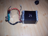
The big connector at the secondairy side was broken and had to be replaced.
The transformer was successfully tested in my working IBM 3277-1 in the Netherlands.
It was then shipped to Denmark waiting for my second visit at the DDHF.
This visit was planned for end September 2014.
Jørgen had emailed me earlier that the IBM 3277-1 stopped working again after a plof and some smoke.
First I opened the unit and started replacing the old ferro transformer and capacitor as planned.
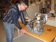
The IBM 3277 still with the old transformer.
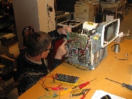
Me testing the new transformer under load.
When replaced, I started looking for anything susperious. The cause of the plof/smoke was quicky found.
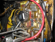
An 32 uF elco 'exploded' on the analog board.
I removed the elco and cleaned the bord a good as possible from any collateral damage.
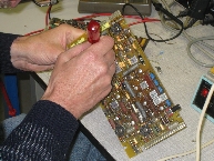
Replaced the elco and finger crossed that it would work again.
No luck, the board was still broken. Unfortunately IBM never published any schematics of this board.
Fault finding at component component level becomes then almost impossible. It RIP.
Plan B: replace the board with a spare one, but it had a hard short circuit in the +34V power line.
An IBM tantaal capacitor (0.68 uF 50V pn 2414883) was the guilty one and was replaced.
Finger crossed again:
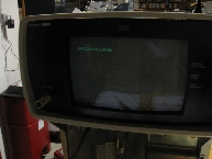
It works again and at 230V AC !
During all this repair work the connector at the top of the PCB was broken (old brittle plastic) and had to be replaced.
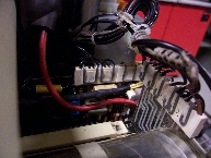
Replaced connector.
IBM 3340 disk drives
The DDHF has two IBM 3340 disk drives. A red and a blue unit.
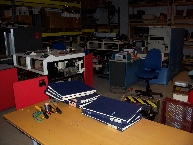
During my previous visit Jorgen and I decided to try powering-up the blue one first because DDHF has a blue CPU unit.
Then we hit a brick wall. The -4V power supply was only able to deliver approx. -2V.
Some parts from the red unit where used to bypass the problem, but no luck.
Now we started with the red unit.
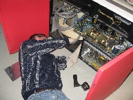
Me placing some parts back from the blue unit into the red unit.
Next we checked if all the logic cards in the A-gate where in the right slot with the correct part number.
Here we discovered that the terminator card in slot A1A3 was missing (p/n 5863806).
Here is a picture of the card (thanks to Christian Corti who provided this picture).
Anyway we connected power and we switched on power, immediately two(!) circuit breakers tripped.
One in the -12V and the other in the -24V circuit.
Again two IBM tantaal capacitor (0.68 uF 50V p/n 2414883) where the guilty.
Two spare cards where used to solve this problem. The unit now powered up without any CB trip.
This red unit still contained two IBM 3348 Data Modules (DM).
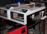
Probably the unit was powered off during de-installation without properly unloading the DM's first.
The IBM MAP chart instructs to "insert bobbin rod" to release the DM's. It took us some time to find out what IBM meant with this.
The DM's where now unloaded and we noticed that some lights where not working, most lamps (GE 757 24V) where broken or even missing.
When setting the "Start/Stop" switch to ON, the DM was loaded and the drive motor started spinning.
The manaul says that the READY light will be turned on within 30 sec after starting the drive.
No luck. (we checked that the READY lamp was ok). The other drive gave the same result.
Looking in the IBM manuals the DM load sequence goes through the following states:
The IBM 3340 manuals are online available at: ftp://129.69.211.2/pub/cm/ibm/ibm4331/3340/
I was able to determine that load sequence made it to state 2. It was not clear if an error occurred in state 2 or while going to state 6.
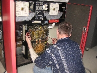
The IBM manuals instructs you to run microdiagnostic 'AC' for more fault information. For this the 3340 unit must be connected to a CPU.
Now we hit a brick wall again: the terminator card for the internal string bus is missing. The chance ever finding this card is very slim.
Fortunately this card is not very high tech and looking at the IBM ALD's it can be rebuild.
The only problem is that IBM uses two types of terminator for SLT lines in their equipment:
- only a 90 Ohm or a 135 Ohm resistors connected to ground.
OR
- an 120 / 360 Ohm resistor network connected to ground and +12V.
I don't know which type has to be used in the IBM 3340. Any information is welcome.
When reading the IBM manuals abit further, I found the procedure for attaching an IBM 3344 drive:
I will plan a third visit to the DDHF when this terminator card is found or reproduced.
Hopefully we can then IPL the CPU with the SCP (System Control Program) and may be even start CCP (Communication Control Program).
Will be continued.
This is the blog of my second visit. Click here for the blog of my first visit.
IBM 3277-1 terminal
Since my first visit the IBM 3277-1 operator console only worked at approx 80V AC without blowing a fuse.
Something was wrong with the ferro transformer or the connected capacitor.
I was very lucky the buy a IBM transformer and capacitor with the same part number on German eBay.

The big connector at the secondairy side was broken and had to be replaced.
The transformer was successfully tested in my working IBM 3277-1 in the Netherlands.
It was then shipped to Denmark waiting for my second visit at the DDHF.
This visit was planned for end September 2014.
Jørgen had emailed me earlier that the IBM 3277-1 stopped working again after a plof and some smoke.
First I opened the unit and started replacing the old ferro transformer and capacitor as planned.

The IBM 3277 still with the old transformer.

Me testing the new transformer under load.
When replaced, I started looking for anything susperious. The cause of the plof/smoke was quicky found.

An 32 uF elco 'exploded' on the analog board.
I removed the elco and cleaned the bord a good as possible from any collateral damage.

Replaced the elco and finger crossed that it would work again.
No luck, the board was still broken. Unfortunately IBM never published any schematics of this board.
Fault finding at component component level becomes then almost impossible. It RIP.
Plan B: replace the board with a spare one, but it had a hard short circuit in the +34V power line.
An IBM tantaal capacitor (0.68 uF 50V pn 2414883) was the guilty one and was replaced.
Finger crossed again:

It works again and at 230V AC !
During all this repair work the connector at the top of the PCB was broken (old brittle plastic) and had to be replaced.

Replaced connector.
IBM 3340 disk drives
The DDHF has two IBM 3340 disk drives. A red and a blue unit.

During my previous visit Jorgen and I decided to try powering-up the blue one first because DDHF has a blue CPU unit.
Then we hit a brick wall. The -4V power supply was only able to deliver approx. -2V.
Some parts from the red unit where used to bypass the problem, but no luck.
Now we started with the red unit.

Me placing some parts back from the blue unit into the red unit.
Next we checked if all the logic cards in the A-gate where in the right slot with the correct part number.
Here we discovered that the terminator card in slot A1A3 was missing (p/n 5863806).
Here is a picture of the card (thanks to Christian Corti who provided this picture).
Anyway we connected power and we switched on power, immediately two(!) circuit breakers tripped.
One in the -12V and the other in the -24V circuit.
Again two IBM tantaal capacitor (0.68 uF 50V p/n 2414883) where the guilty.
Two spare cards where used to solve this problem. The unit now powered up without any CB trip.
This red unit still contained two IBM 3348 Data Modules (DM).

Probably the unit was powered off during de-installation without properly unloading the DM's first.
The IBM MAP chart instructs to "insert bobbin rod" to release the DM's. It took us some time to find out what IBM meant with this.
The DM's where now unloaded and we noticed that some lights where not working, most lamps (GE 757 24V) where broken or even missing.
When setting the "Start/Stop" switch to ON, the DM was loaded and the drive motor started spinning.
The manaul says that the READY light will be turned on within 30 sec after starting the drive.
No luck. (we checked that the READY lamp was ok). The other drive gave the same result.
Looking in the IBM manuals the DM load sequence goes through the following states:
- State 0 - Wait. (drive motor stopped, DM unloaded, door unlocked, switch in OFF position.)
- State 1 - Load the DM, unlock the carriage and lock the door. (switch in ON position)
- State 3 - Get the drive motor up to speed.
- State 2 - Move the carriage from the Home position to track 0.
- State 6 - Access data (Read and Write) READY light on.
The IBM 3340 manuals are online available at: ftp://129.69.211.2/pub/cm/ibm/ibm4331/3340/
I was able to determine that load sequence made it to state 2. It was not clear if an error occurred in state 2 or while going to state 6.

The IBM manuals instructs you to run microdiagnostic 'AC' for more fault information. For this the 3340 unit must be connected to a CPU.
Now we hit a brick wall again: the terminator card for the internal string bus is missing. The chance ever finding this card is very slim.
Fortunately this card is not very high tech and looking at the IBM ALD's it can be rebuild.
The only problem is that IBM uses two types of terminator for SLT lines in their equipment:
- only a 90 Ohm or a 135 Ohm resistors connected to ground.
OR
- an 120 / 360 Ohm resistor network connected to ground and +12V.
I don't know which type has to be used in the IBM 3340. Any information is welcome.
When reading the IBM manuals abit further, I found the procedure for attaching an IBM 3344 drive:
- Move the internal bus terminator card to the newly attached unit.
- Move two jumpers for the PLO/VFO and read/write line termination.
- Remove a jumper on the power-on sequence card.
I will plan a third visit to the DDHF when this terminator card is found or reproduced.
Hopefully we can then IPL the CPU with the SCP (System Control Program) and may be even start CCP (Communication Control Program).
Will be continued.